When to use this
For an LED module with display problems such as missing pixels, damaged pixels, or pixels showing the wrong color.
Steps
-
Move cables away from the work area. Disconnect only the cables that block access and note where each connector belongs.
-
Remove the four screws securing the power supply to the clock body, two on each side.
-
Move the power supply only far enough to expose the module. Do not pull on its connected wires.
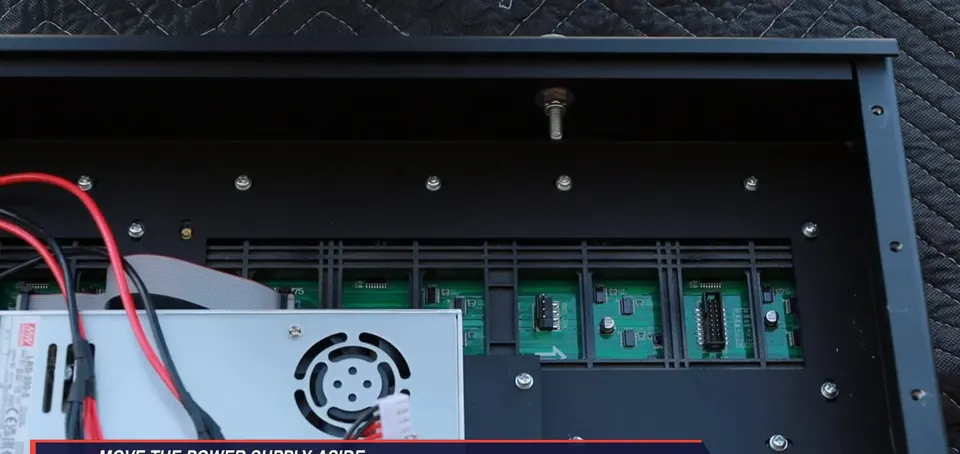
Move the power supply for access -
Remove the mounting screws securing the LED module you are replacing (the upper-right module in the video), then lift the module straight out.
-
Disconnect the module ribbon cable and power connector. Pull on the connector housings, not the wires.
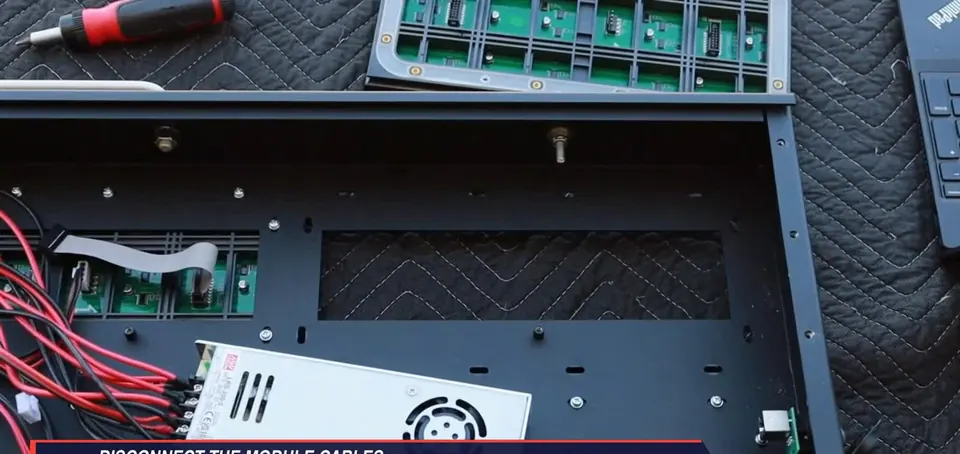
Disconnect module cables -
Match the replacement to the surrounding module orientation. The printed circuit-board arrow must point to the right.
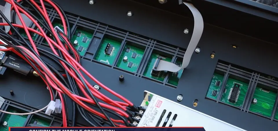
Printed arrow points right -
Place the replacement into the opening, align the mounting points, and tighten the module screws evenly. Do not overtighten.
-
Reconnect the module power connector and ribbon cable until fully seated.
-
Return the power supply and cables to their original positions. Reinstall all four power-supply screws.
-
Confirm that no cable is loose or pinched before closing the housing.
Important
- Four power-supply mounting screws: two per side.
- Printed module arrow points right.
- Pull connectors by their housings.
Check when done
Module hardware is secure, power and ribbon connectors are fully seated, and no cable is loose or pinched.
Still not working?
Email support@finishedresults.com. Tell us you completed procedure 05 and what you saw when you checked your work. Replacement parts are ordered the same way.